

Compressed air is an efficient source of energy provided that its production, treatment and distribution components are perfectly matched with one another. Moreover, correct system design and appropriate sizing and installation of the air distribution network are also essential.
1. Economical compressed air production
When the cost of energy, cooling medium, maintenance and equipment depreciation is taken into account, the cost of each cubic metre of air produced, depending on the compressor size, utilisation, condition and model, is between 0.5 and 2.5 cents (Euro).
Many production facilities place great importance on highly efficient compressed air production. This is one of the key reasons why fluid/oil-cooled rotary screw compressors have become so popular: They can reduce compressed air production costs by as much as 20 % compared with other types of compressor.
2. The influence of air treatment on the air main
However, less consideration is given to ensuring application specific compressed air treatment. This is a shame, since only correctly treated air can reduce the maintenance costs of air consumers and associated pipework.
Wherever pipework conveys moisture-laden, non-dried compressed air, it is essential that corrosion-resistant pipework is used. Care should also be taken to ensure that inadequate pipework does not negatively impact the compressed air quality achieved by the treatment system.
a) Refrigeration dryers reduce maintenance requirement
Refrigeration drying provides an air quality sufficient to meet 80% of all applications. Refrigeration dryers often eliminate the pressure losses associated with in-line filters in the air network and consume only approx. 3% of the energy that the compressor would otherwise use to make up for these pressure losses.
In addition, the saving in costs for maintenance and repair of air-consuming equipment and pipework can easily amount to ten times the average cost of refrigeration drying.
b) Space-saving combination systems
For smaller or local applications, spacesaving compressed air packages comprising a rotary screw compressor, a refrigeration dryer and air receiver (fig. 1) are also available.
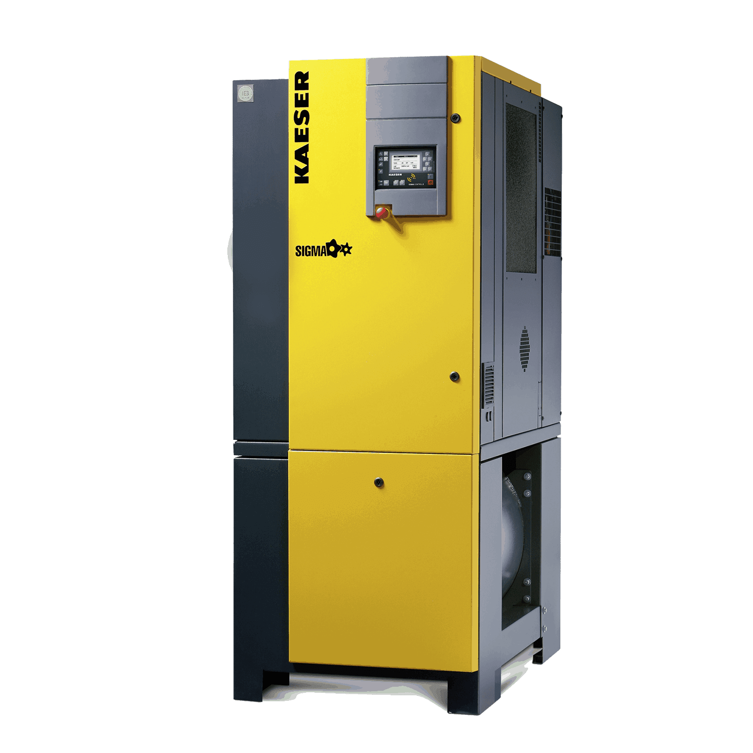
Fig. 1: The all-in-one AIRCENTER compressed air package for space-saving compressed air production, treatment and storage
3. Designing and installing an air distribution network
When designing a new compressed air installation, one of the key factors to consider is whether it should be designed as a centralised or a decentralised system.
A centralised system is usually suitable for smaller and mid-sized businesses, since many of the problems that occur in larger systems do not generally arise, e.g. high installation cost, freezing of inadequately insulated external piping in winter, or increased pressure drops caused by long sections of piping.
a) Correctly sizing the network
A calculation must always be used to correctly size air distribution piping. This calculation is based on the rule that the maximum pressure drop between the compressor and the air-consuming equipment (including standard air treatment, i.e. refrigeration drying) should be no greater than 1 bar. The following individual pressure losses should be taken into account (fig. 2):
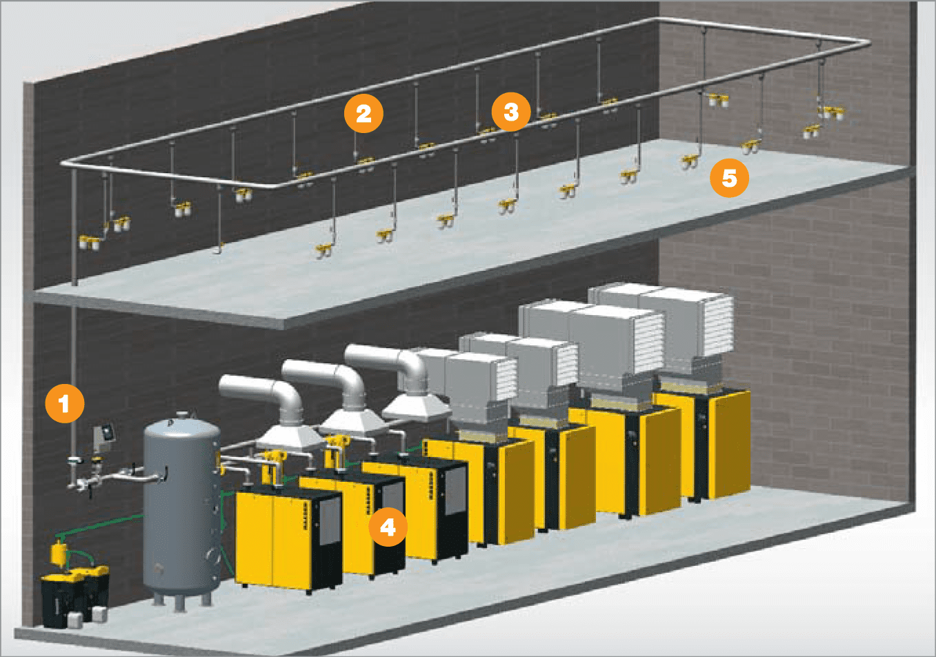
The importance of calculating the pressure drops in the individual piping areas becomes apparent when they are itemised in this way. Shaped components and shut-off units should also be taken into consideration. Therefore it is not enough to just simply input the number of metres of straight piping into a calculation formula or table, as the actual technical flow length of the piping has to be determined.
During the initial system-planning phase however, the calculation figure for all shaped components and shut-off units is usually unclear. Hence, the flow length of the piping is calculated by multiplying the number of metres of straight piping by a factor of 1.6. The piping diameter can then be easily determined by referring to tried and tested formulas (fig. 3) or design diagrams.
Approximation formula:
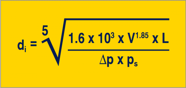
di = Internal pipe diameter (m)
ps = System pressure (absolute in Pa)
L = Nominal length (m)
V = Flow volume (m³/s)
∆p = Pressure loss (Pa)
Total max. 0,80 bar
b) Installing energy-saving pipework
In order to save energy the pipe layout should be as straight and direct as possible. For instance, one can avoid bends in laying pipe work around an obstacle by repositioning the run in a straight line alongside it.
Sharp, 90° corners cause high pressure drops and should be replaced with large-radius elbows. Instead of the commonly-used water shut-off valves, ball or butterfly valves with full through-flow bores should be used.
In wet pipework areas, e.g. only the compressor room in the case of modern air systems, pipe connections to and from the main line should be made from above or at least from the side.
The main line should have a drop of 2 in 1000. The possibility of connecting a condensate drain should be provided at the lowest point in this line. In dry areas the pipeline can be horizontal with branch lines connected directly downwards.
c) Which piping material
No specific recommendation can be made with regard to material properties. However, due to the high thermal loads associated with compressors, metallic piping should always be used.
The investment price alone provides little help in making a decision, as galvanised steel, copper and plastic pipes all cost about the same when material and installation costs are added. Stainless steel piping is about 20% more expensive. However, more efficient processing methods have allowed prices to drop in recent years.
Most manufacturers offer tables in which the optimal conditions for every pipe material are given. It is advisable to study tables such as these before making a decision, to take into account the loads placed on the air main during normal operation in the future and then to create specifications for the pipework accordingly. This is the only way to ensure a truly effective air main system.
d) Important – correct jointing
The pipes should be jointed either through welding, with adhesive or screwed with adhesive. It is especially important that the jointing is correctly carried out to ensure a mechanically sound and leak-proof joint, even if it is difficult to take them apart again.