

The pipe network not only distributes compressed air within a company’s facilities, but also connects the compressors and other components of the compressed air installation to the whole system.
In order to ensure best possible efficiency and reliability , several important factors should be taken into consideration when installing the system.
The pipe network should usually be laid out in such away that the pressure loss caused by the piping remains below 0.01 bar at full flow capacity. It is also advisable to use only metal piping, as it can cope with differing thermal loads.
Connection of compressed air distribution piping
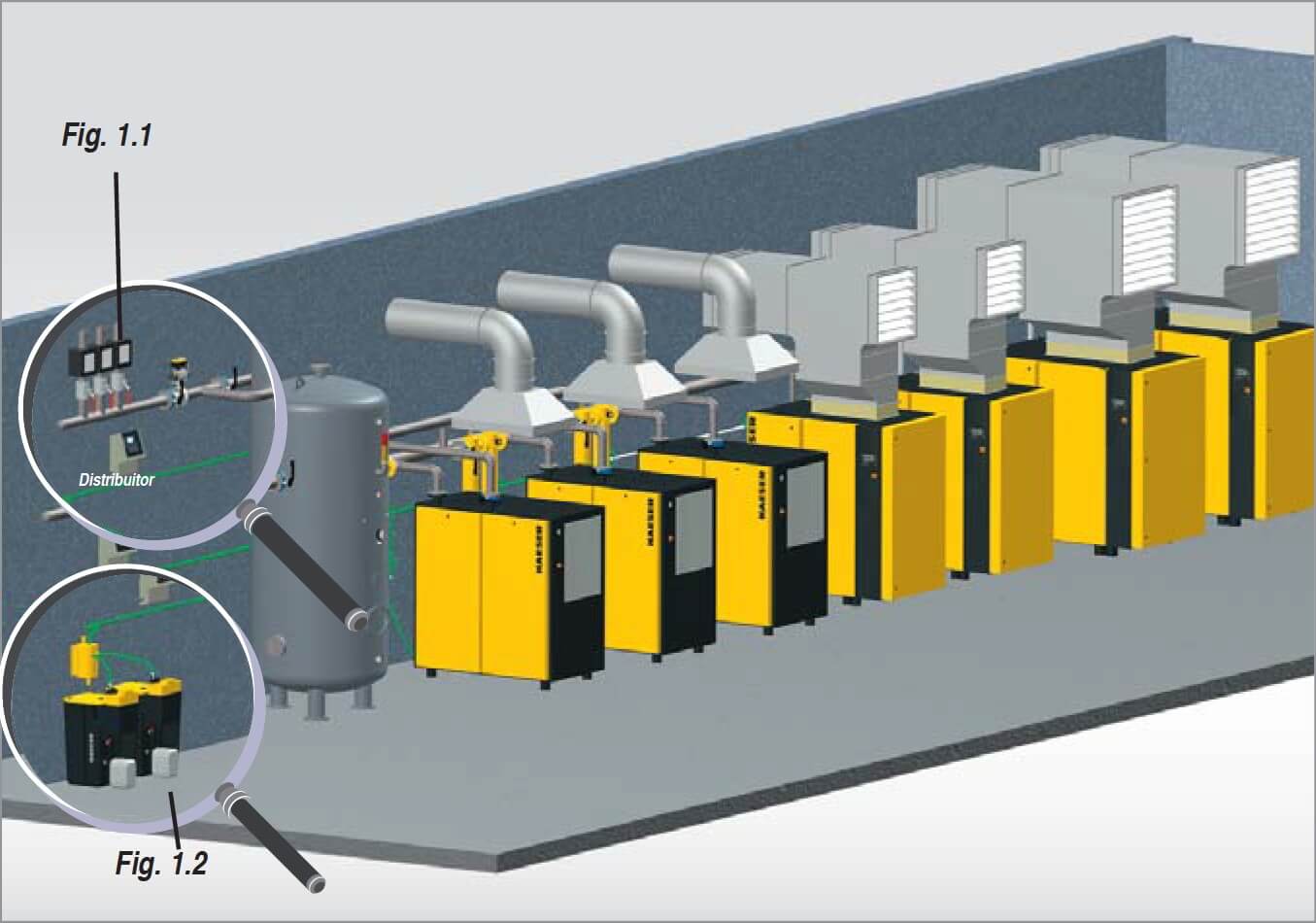
The best way to connect the piping from the compressor station to the air distribution network is to use a collector.
The collector acts as a central feed-off point for all distribution lines (fig. 1.1). and, if necessary, allows the compressed air supply to be shut down for specific operating areas.
Installation in the „moist air sector”
Installation of a condensate collector in the so-called „moist air sector”, i.e. the piping sections located downstream from the compressors and upstream from the air dryers, should be avoided if at all possible.
Otherwise, the piping must slope towards the condensate collector, which must be drained via a specifically dedicated condensate drain (fig. 2).
Correct component connection
The individual components of the compressor station (compressors, dryers etc.) should be connected to the main air line from above. Connection from the side is also possible with pipe diameters from DN 100 (fig. 3 a/b).
Compressor connection
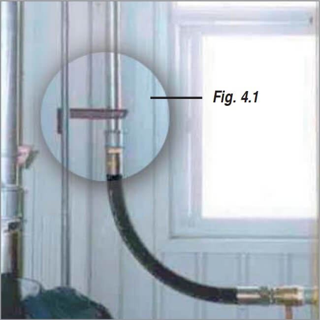
Flexible connections should be used to connect the compressors to the air distribution network in order to avoid transmission of vibrations. Hose connections are suitable for pipe widths < DN 100 (fig. 4). A vibration-absorbing fastening is attached between the hose and the first pipe bend to ensure that these forces are not transferred to the piping (fig. 4.1).
For pipe diameters > DN 100 axial compensators must be used instead of hoses (fig. 3b) to implement the vibration-dampening connection between the compressor and pipeline system.
Correct condensate drainage
Reliable condensate removal is essential to ensure optimised compressed air system performance and availability. There are a few errors worth avoiding, particularly when it comes to installing compressed air lines.
Despite today’s advanced drainage technology, the connection lines used to connect these condensate treatment systems are often incorrectly installed. These problems can be easily avoided however, by following the simple tips below:
Shut-off the condensate drain
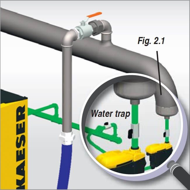
Condensate drains should be able to be shut-off on either side via a ball valve so that they can be easily removed from the compressed air system should maintenance work need to be carried out (fig. 2.1).
Correct connection size
The air-main collector should have at least a ½” connection in order to prevent unnecessary back-pressure.
Connection from above
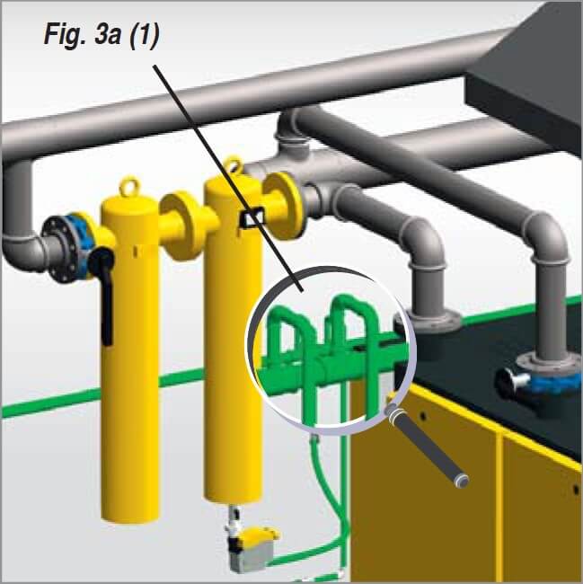
The air-main collector should be connected to the condensate lines from above so that the drainage points do not influence one another (fig. 3a (1)).
Sloping, pressure-free line
The condensate collector should always be installed at a gradient and should not be under pressure. Condensate drains from various system components (e.g. centrifugal separator, air receiver, refrigeration dryer, air filters) operating at different pressure levels should discharge only into a system like this.
If this is not possible, then various connection points on the condensate treatment equipment (Aquamat) should be used.
Multiple treatment units
If, due to large volumes of condensate, it is necessary to use several treatment units, then the main condensate line should be connected via a flow distributor (fig. 1.2).
System pressure above 15 bar
For systems with pressures above 15 bar, a separate high-pressure relief chamber should be used before the condensate is drained into the treatment unit.