

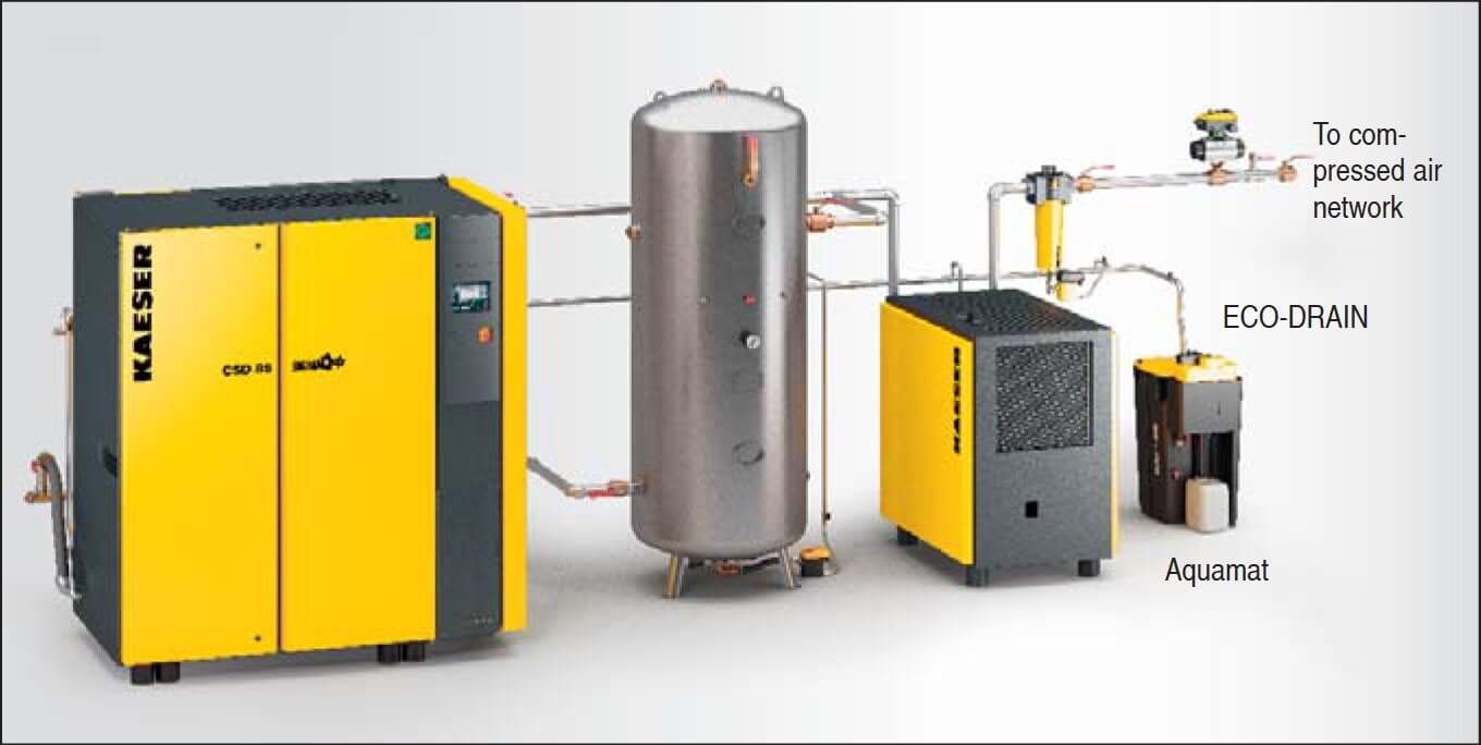
Condensate from industrial compressors is an unavoidable by-product of compressed air production. We explained how, under average conditions, a 30 kW compressor with a FAD of 5m³/min produces approximately 20 litres of condensate per shift. This liquid must be removed from the air system to prevent system failures, costly production downtime and corrosion. In this chapter we explain how to drain condensate correctly and achieve significant cost-savings at the same time.
1. Condensate drainage
Condensate, contaminated by diverse pollutants, collects at certain points in every air system (Fig. 1). Reliable condensate drainage is therefore essential, otherwise air quality, operational reliability and compressed air system efficiency can be seriously affected.
a) Condensate collection and drainage points
Initially, mechanical elements of the air system serve to collect and drain condensate from compresses air. 70 to 80 % of all the condensate is collected at these points – provided the compressors are fitted with effective after-cooling.
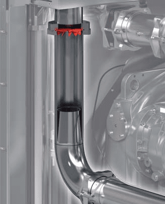
Separator centrifugal:
This is a mechanical separator that separates the condensate from the air by means of centrifugal force (Fig. 2). In order to ensure optimum performance, each compressor should be equipped with its own dedicated centrifugal separator.
Intercoolers:
On two-stage compressors equipped with intercoolers, the condensate also collects at the intercooler’s separator.
Air receivers:
As well as its main function as a storage or buffer tank, the air receiver separates condensate from the air by gravity (Fig. 1). If sufficiently sized (compressor FAD in m³/min divided by 3 = air receiver size in m³), the air receiver is just as effective as a centrifugal separator.
In contrast to the centrifugal separator, however, the air receiver can be used in the main air line of the compressed air system, providing the air inlet is at the bottom and the outlet is at the top. Moreover, due to its large heat dissipation surface area, the air receiver additionally cools the air thereby enhancing condensate separation yet further.
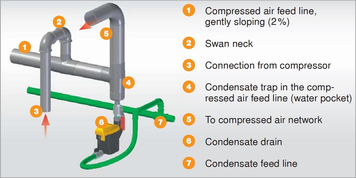
Water-traps in the air line:
To avoid undefined condensate flow, the air line should be designed so that all inlet and outlet points are are connected from above or from the side.
Defined condensate outlets leading downwards, so-called water traps, allow condensate to be removed from the main air line. With correct design and an airflow of 2 to 3 m/s a water trap (Fig. 3) in the wet area of the air system separates condensate just as effectively as an air receiver (Fig. 1).
b) Compressed air dryers
As well as those already mentioned, there are additional collecting and drainage points to be found within the compressed air drying process.
Refrigeration dryers:
Further condensate is separated in the refrigeration dryers due to the drying effect of cooling the compressed air.
Desiccant dryers:
Due to the considerable cooling effect of the air line, condensate can collect at the pre-filter in the inlet to the desiccant dryer. In the desiccant dryer itself, water only exists as vapour because of the partial pressure conditions prevailing in the dryer.
c) Local separators
If no central drying system exists, large quantities of condensate collect at the local separators fitted just upstream from air-consuming equipment. However, these systems are exceptionally maintenance-intensive.
2. Drainage systems
At present, three systems are mainly used:
a) Float drains
The float drain is one of the oldest drainage systems and replaced manual drainage, which was both inefficient and highly unreliable. However, even condensate drainage using the float principle (Fig. 4) proved to be extremely susceptible to malfunction due to dirt and contaminants in the compressed air.
b) Solenoid valves
Time-controlled solenoid valves are more reliable than float drains, but they have to be checked regularly for clogging and contamination. Incorrectly adjusted valve opening periods can cause air losses and increased energy consumption.
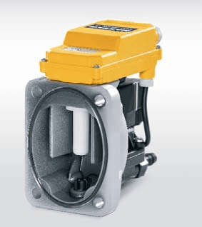
c) Condensate drains with level-sensing control
Nowadays, drains equipped with intelligent level-sensing control are predominantly used (Fig. 5). They have the advantage that the float, which is highly susceptible to faults, is replaced by an electronic sensor. This eliminates the faults caused by dirt, or mechanical wear associated with float drains.
Furthermore, air losses (which also occur with float valves) are prevented by the automatically controlled valve opening periods. Additional benefits include automatic self-monitoring and the ability to send signals to a central control system.
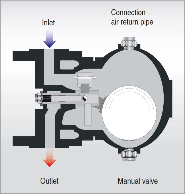
d) Correct installation
A short length of pipe containing a shut-off valve should be fitted between the condensate separating system and the condensate drain (Figs. 2 and 3). This allows the drain to be isolated during maintenance and the compressed air system can remain in operation.