By correctly matching compressed air delivery to fluctuating compressed air demand, energy-intensive, and therefore costly, partial load phases can be virtually eliminated.
The right compressor controller consequently plays a key role in ensuring optimum energy efficiency.
Compressors operating at less than 50 % load should set off loud alarm bells with regards to serious energy wastage.
Many users are not even aware of this fact because their compressors have an indicator showing only the hours in operation but not the hours under load.
Perfectly matched control systems can help by increasing the load factor to over 90 % and by achieving power savings of up to 20 % or more.
1. Internal compresor control
a) Full-load / idle control
Most compressors are fitted with three phase asynchronous drive motors. However, the permissible starting frequency of these motors becomes lower in relation to increased motor size.
This does not correspond to the starting frequency necessary to cut in and cut out compressors with lower switching differentials to meet the actual air demand.
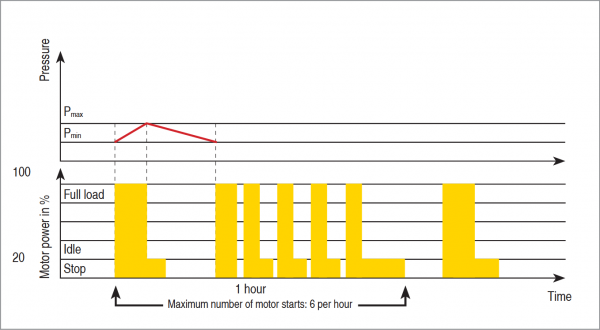
These switching cycles would only unload the pressurised areas of the compressor system. The drive motor, on the other hand, must carry on running for a certain period to avoid exceeding its starting frequency (fig. 1). The power needed to turn the motor during this off-load period must be regarded as a loss.
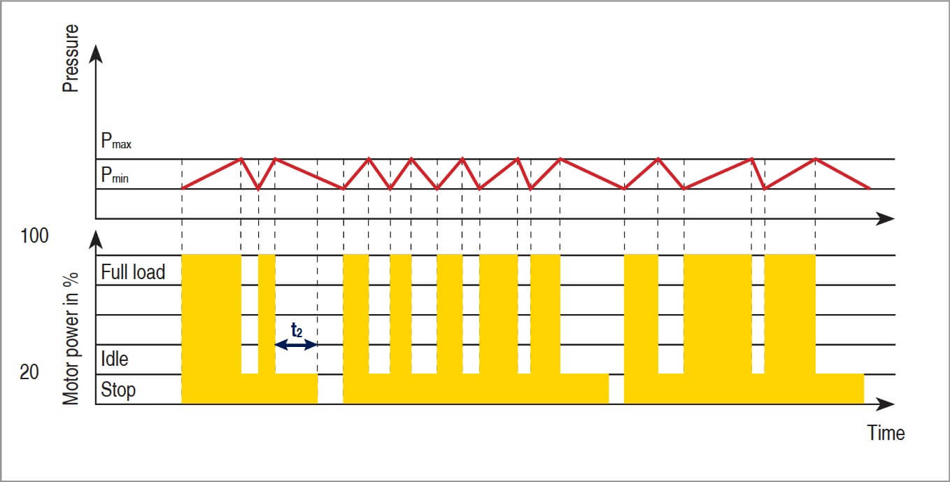
The power consumption of a compressor switched to off-load running is still 20 % of full load drive power.
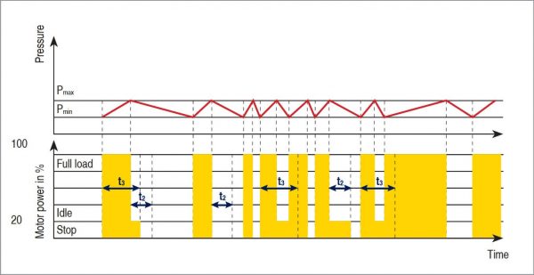
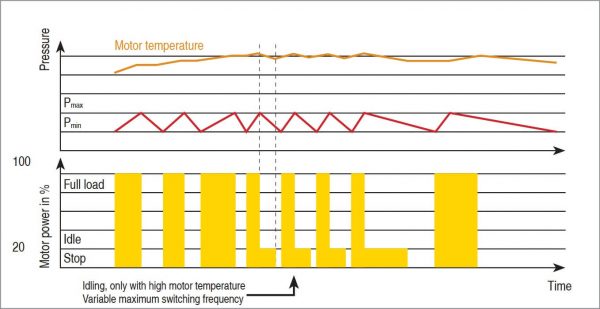
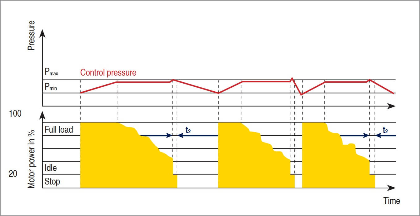
Modern, computer-optimised control systems such as Quadro control with automatic optimal operating mode selection (fig. 2), Dynamic control with drive motor temperature dependent idling (fig. 3) and Vario control with variable calculated idling periods (fig. 4) help to keep costly idling periods to a minimum and ensure maximum motor protection.

Fig. 2: Full load – Idle – Start / stop control with automatic optimal mode selection, so-called Quadro control Fig. 3: Dynamic control, based on Dual control, with drive motor temperature dependent idling 
Fig. 4: Vario control with variable calculated idling periods
Proportional controllers using intake side throttling are not recommended, since the compressor still requires 90 % of the energy it would otherwise need to provide 100% free air delivery, in order to deliver just 50 % of maximum capacity.
b) Variable frequency drive
The efficiency of compressors which are speed controlled by a frequency converter (fig. 5) is inconsistent over the control range. In the control range between 30 and 100% for example, efficiency is reduced from 94 to 86% for a 90k W motor. Added to this are the losses in the frequency converter and the non-linear power characteristic of the compressors.
FC-controlled compressors should be operated in the 40-70% control range: this is where they provide optimal performance. These components should be designed for 100% load.
If variable speed compressors are inappropriately used for an application, they can end up consuming a lot of energy without the user ever being aware of the fact.
This means that variable frequency drive is not a universal remedy in the search for maximum efficiency and energy-saving operation.
2. Classification of air demand
Generally, compressors can be classified according to function into base load, medium load, peak load or standby-units.
a) Base load air demand
Base load air demand is the volume of air that is constantly needed by a production facility.
b) Peak load air demand
In contrast, the peak load is the volume of air demanded at certain peak load times. It varies in volume because of the differing demand from various consumers.
In order to fulfil this wide range of load demands as best as possible, the compressors need to be equipped with individual control systems.
These slave controllers must be capable of maintaining compressor operation, and therefore the supply of compressed air should a defect occur on the master controller.
3. Master control
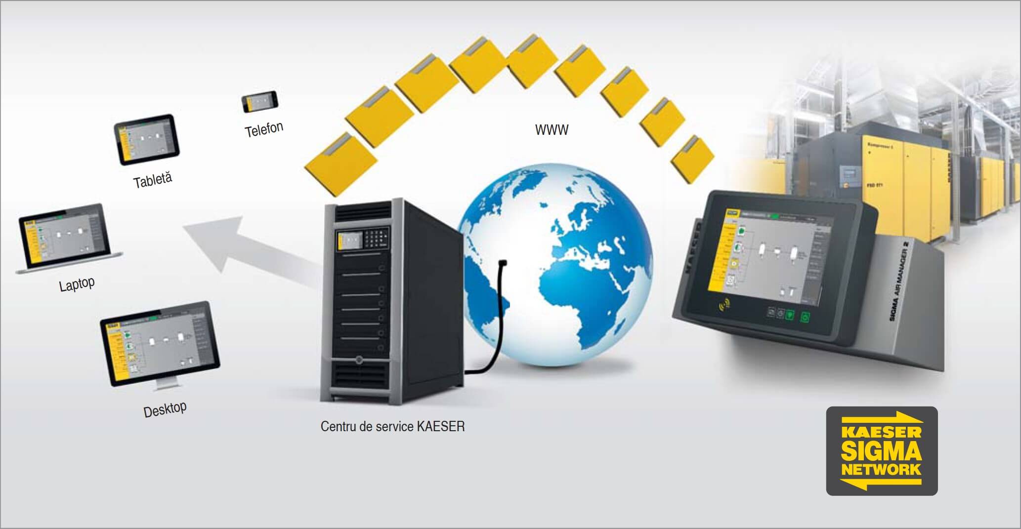
Controlerele centrale moderne, echipate cu software bazat pe web, sunt capabile atât să coordoneze funcționarea compresorului într-o stație de aer comprimat, pentru a asigura o eficiență energetică optimă, cât și să asigure posibilitatea de a aduna date de performanță și documente doveditoare ale eficienței sistemului de alimentare cu aer comprimat.
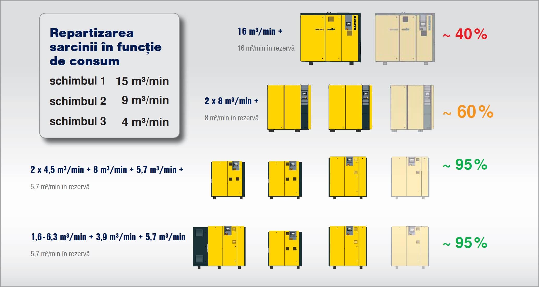
a) System splitting
Splitting is the division of compressors of equal or differing capacities and type of control according to base load and peak load air demand of a production facility (fig. 6).
b) Master controller tasks
Coordination of compressor operation is a demanding and complicated task. Modern master controllers must not only be able to simultaneously activate and deactivate compressors of differing make and size.
Ele trebuie să fie, de asemenea, capabile să monitorizeze necesarul de întreținere al sistemului, să echilibreze orele de funcționare ale echipamentelor și să înregistreze alarmele pentru a minimiza costurile de service și pentru a maximiza fiabilitatea.
c) Correct grading
For a master controller to operate with maximum efficiency, the compressors within the compressed air station must be perfectly graded.
The sum of the air capacities of the peak load machines must therefore be larger than that of the next base load machine to be cut in.
If a peak load machine with variable frequency drive is used, the control range must be larger than the capacity of the next compressor to be cut in. Otherwise the efficiency of the compressed air supply cannot be guaranteed.
d) Secure data transfer
Another important requirement for perfect function and efficiency of a master controller is the safe and secure transfer of data.
It must be ensured that messages are transferable between each compressor and between the compressors and the master controller. In addition, the signal paths must be monitored so that faults such as loss of continuity in a connecting cable are immediately recognised.
The normal transfer methods are:
- Floating relay contacts
- Analogue signals 4 – 20 mA
- Electronic interfaces, e.g. RS 232, RS 485, Profibus DP or Ethernet.
Profibus offers the most advanced data transfer technology. This system can quickly transfer large volumes of data over long distances.
When combined with Ethernet and modern telecommunications technology, connection to standardised computer and monitoring systems is also possible. This means that master controllers do not have to be located in the compressed air installation itself (fig. 7).